Building Ben Eater's 6502 Kit
I recently discovered Ben Eater’s excellent video series on building a 6502-based computer on a breadboard. The 6502 is a pretty famous microprocessor and variants of it were used in the Nintendo, some Ataris, the Apple II, and the Commodore 64 (among others).
I’ve done a bit of hardware stuff before, but mostly at the level of Raspberry Pis, so this was definitely a step up in terms of difficulty for me. Undaunted, I started with the Clock Module:
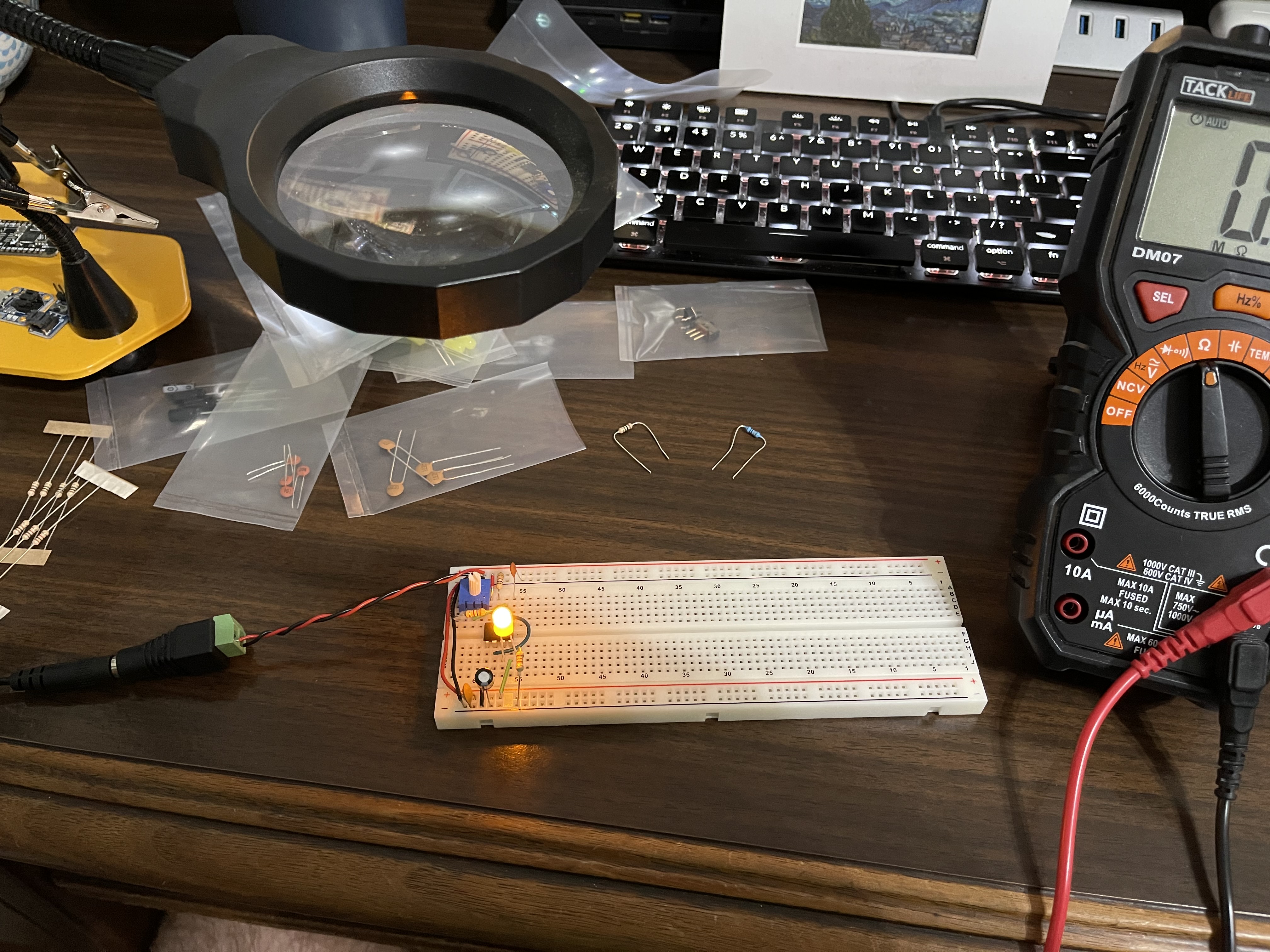
I was able to get it working without too much trouble and definitely learned how to neatly wire up a breadboard (also the value of doing it neatly). Here’s the final verion:
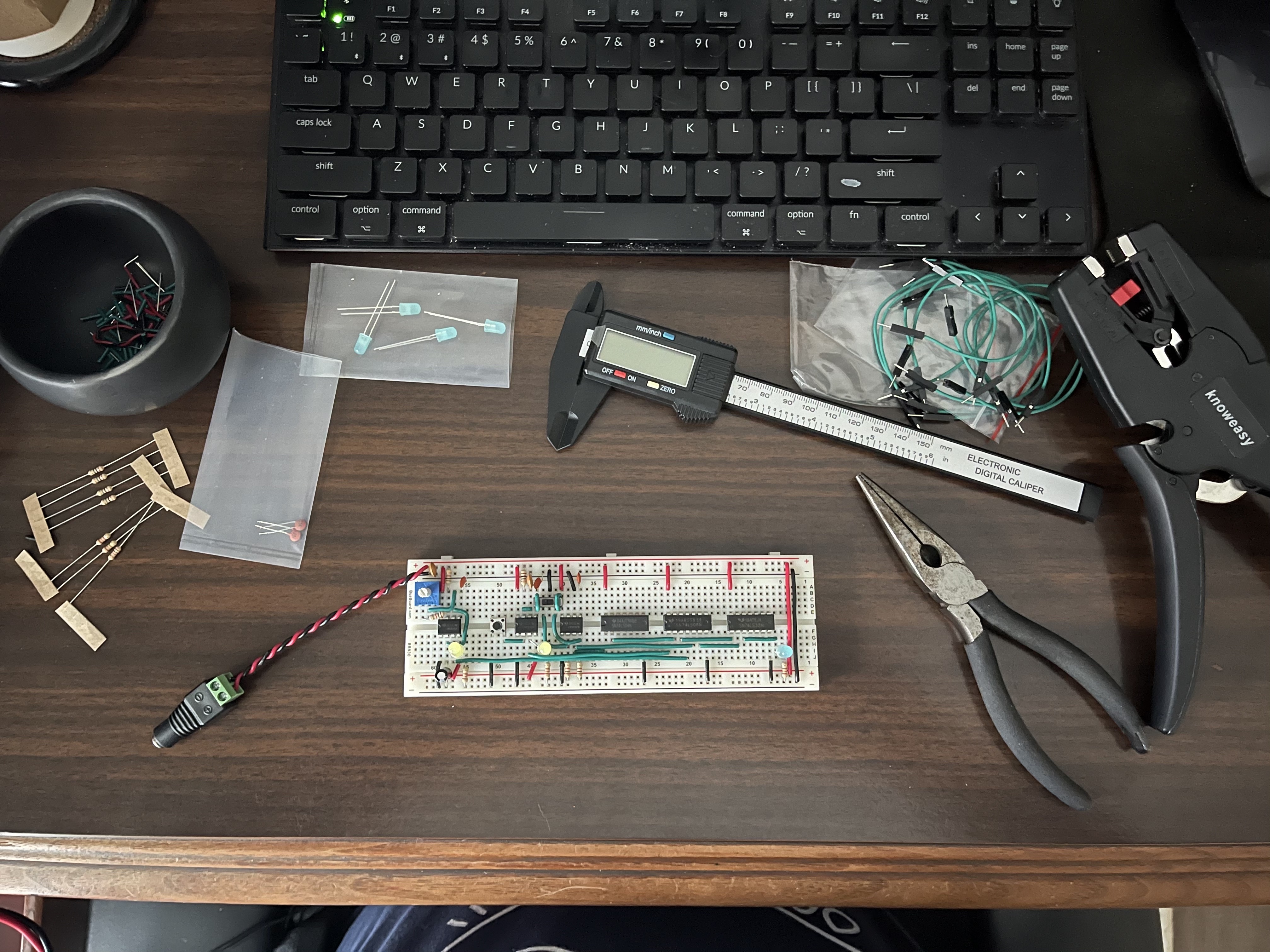
It’s amazing how satisfying just getting an LED to blink at different speeds is! And, yes, that is me using a caliper to measure out the wires. The star of this circuit is definitely the 555 timer, which I took a detour to study for a bit in an attempt to understand it a bit better. I ordered a kit from EvilMadScientist.com that I’m excited about but I haven’t assembled it yet! Now it’s time to get the 6502 installed! You can see it here installed on a second breadboard attached to the clock module:
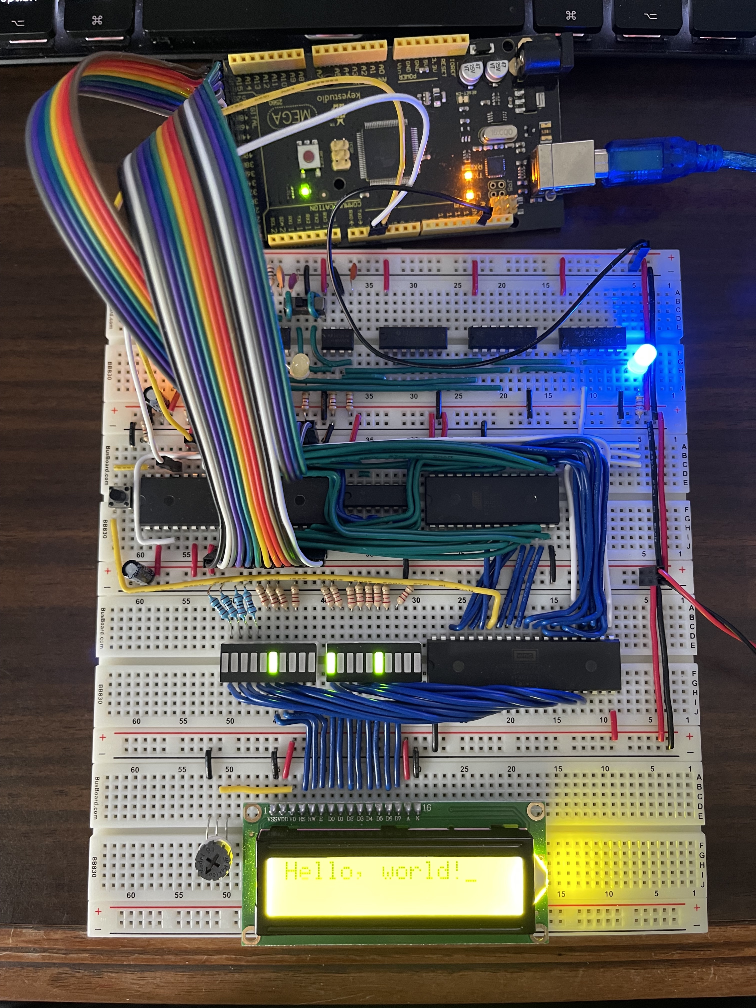
One really cool thing that Ben did in his video series was to use an Arduino to read the contents of the address and data busses so that you’re able to see, in real time, what’s on the bus! Here’s what that looks like all hooked up:
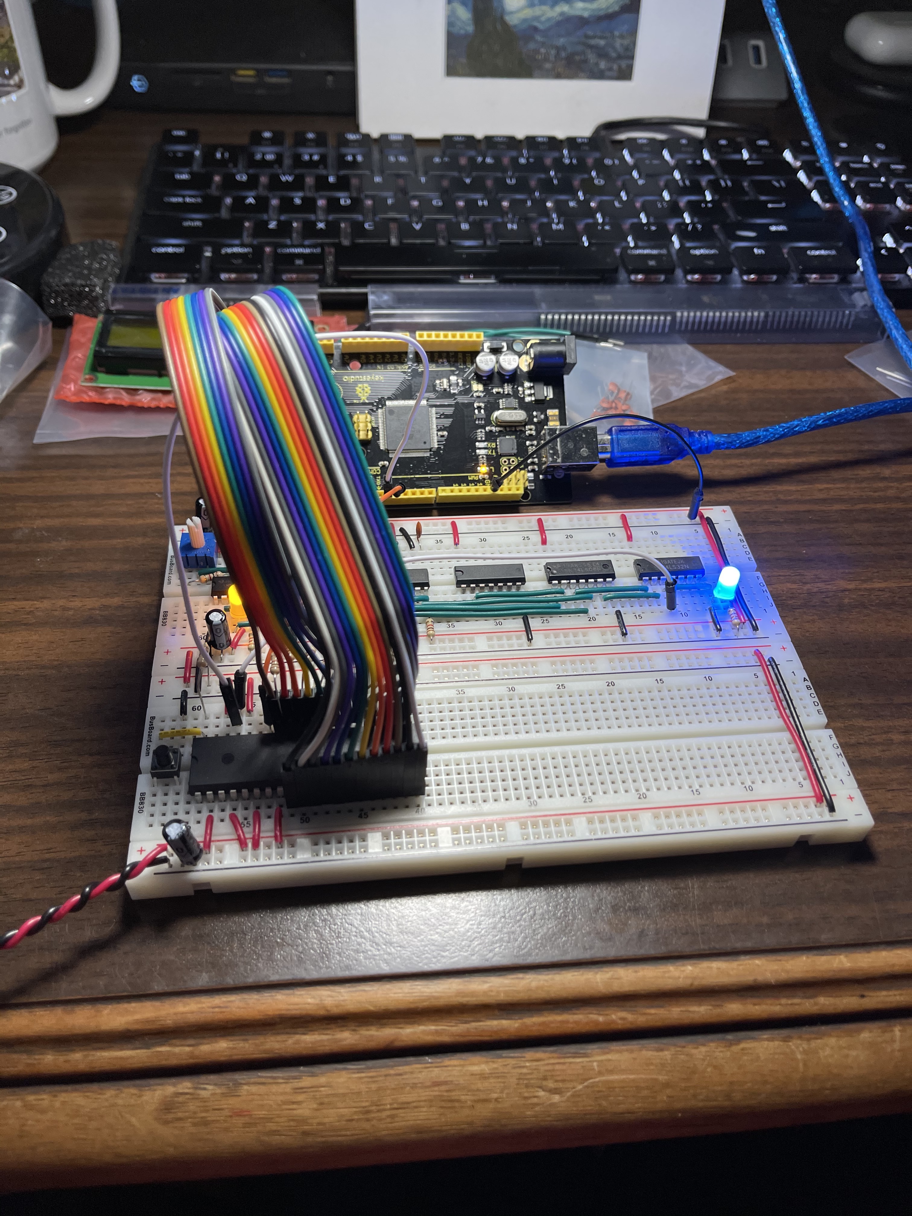
After verifying that things are working at this level, the next step is to hook up an EEPROM to store a program for the 6502 to run. There’s also an interface chip that I installed before taking another photo. You can see the output of that chip on the fancy LEDs above the LCD screen. At this point, I have a rudimentary program running to communicate with the LCD to display “Hello, world!”
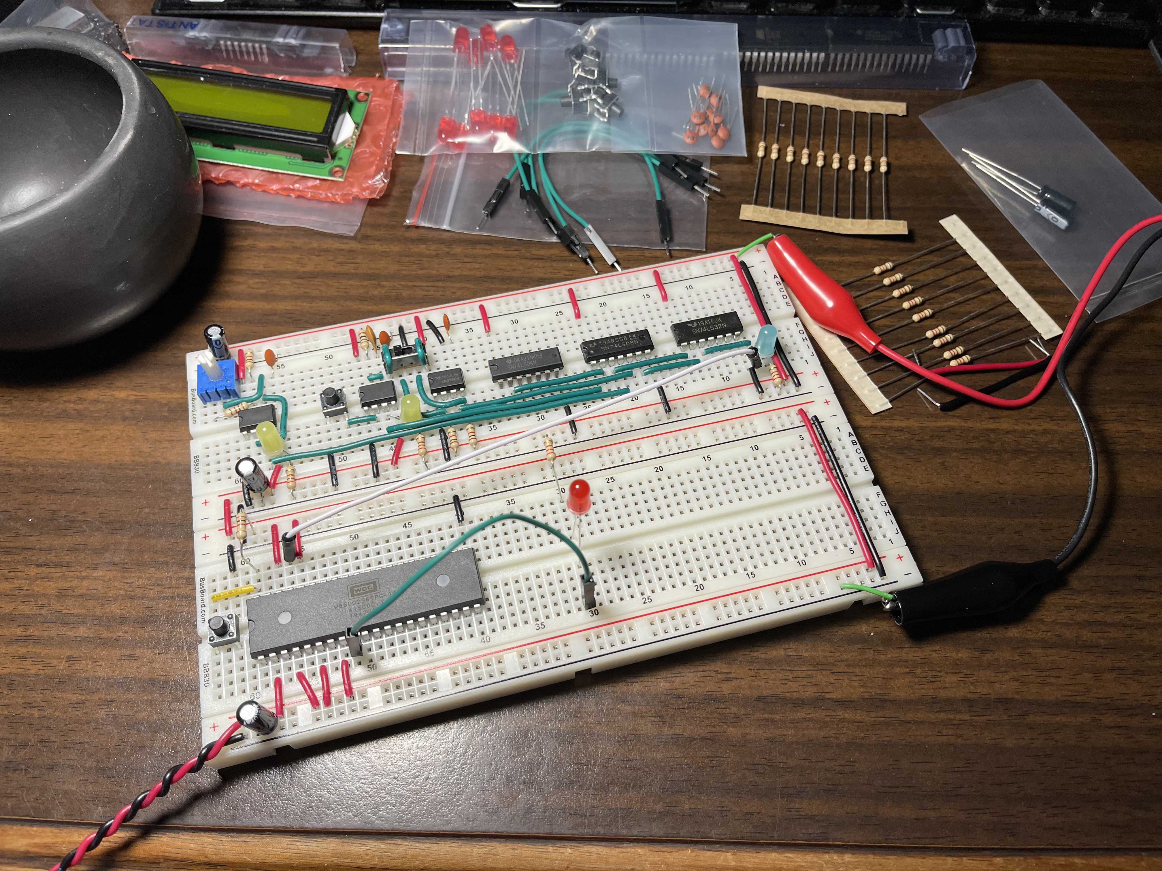
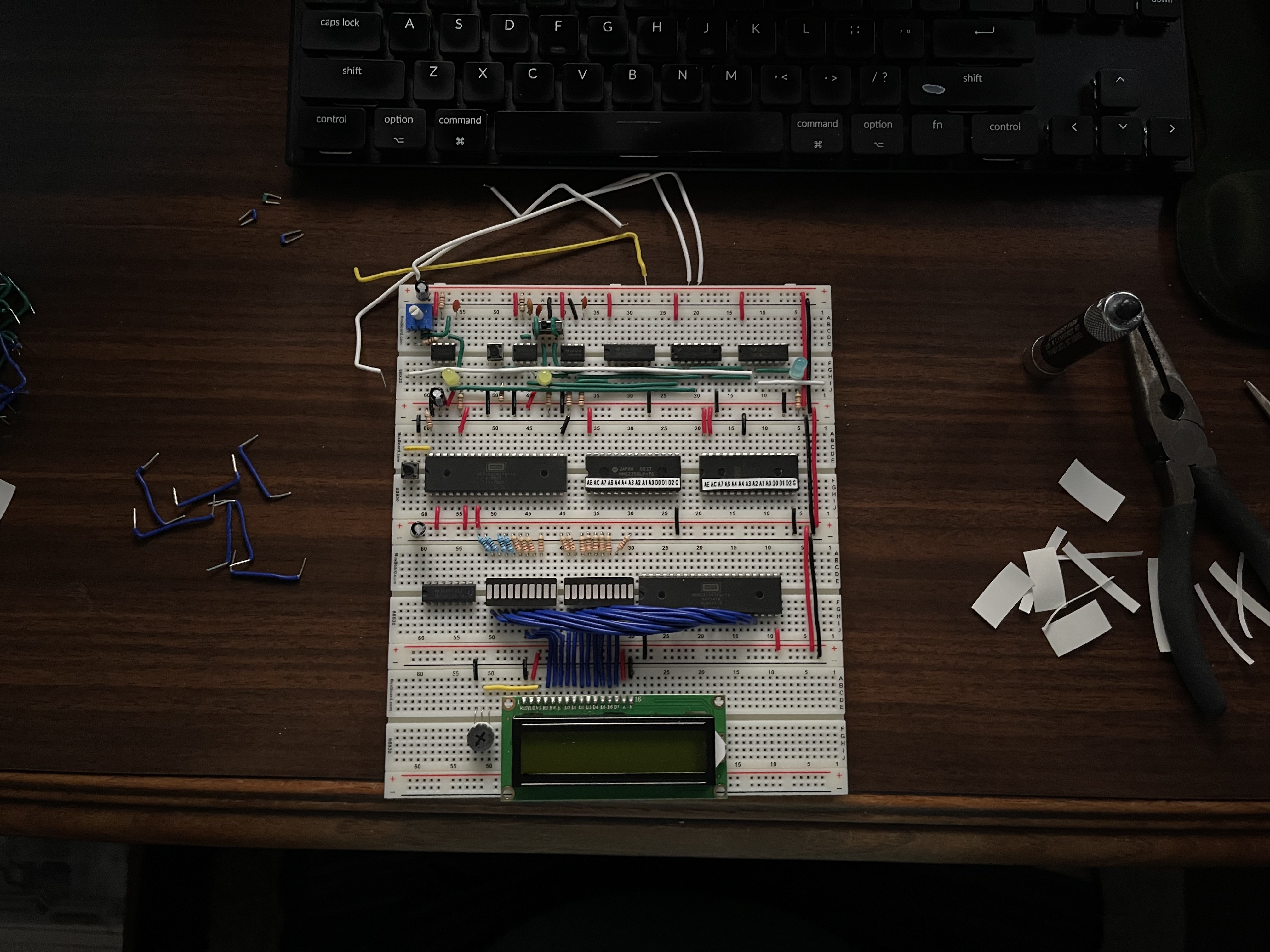
Great success! Now, we’ll install a RAM chip so that we can have a stack, which will enable us to call subroutines. This required moving some chips around to keep things clean, so I had to do a good bit of re-wiring. Here’s the boards before that work started:
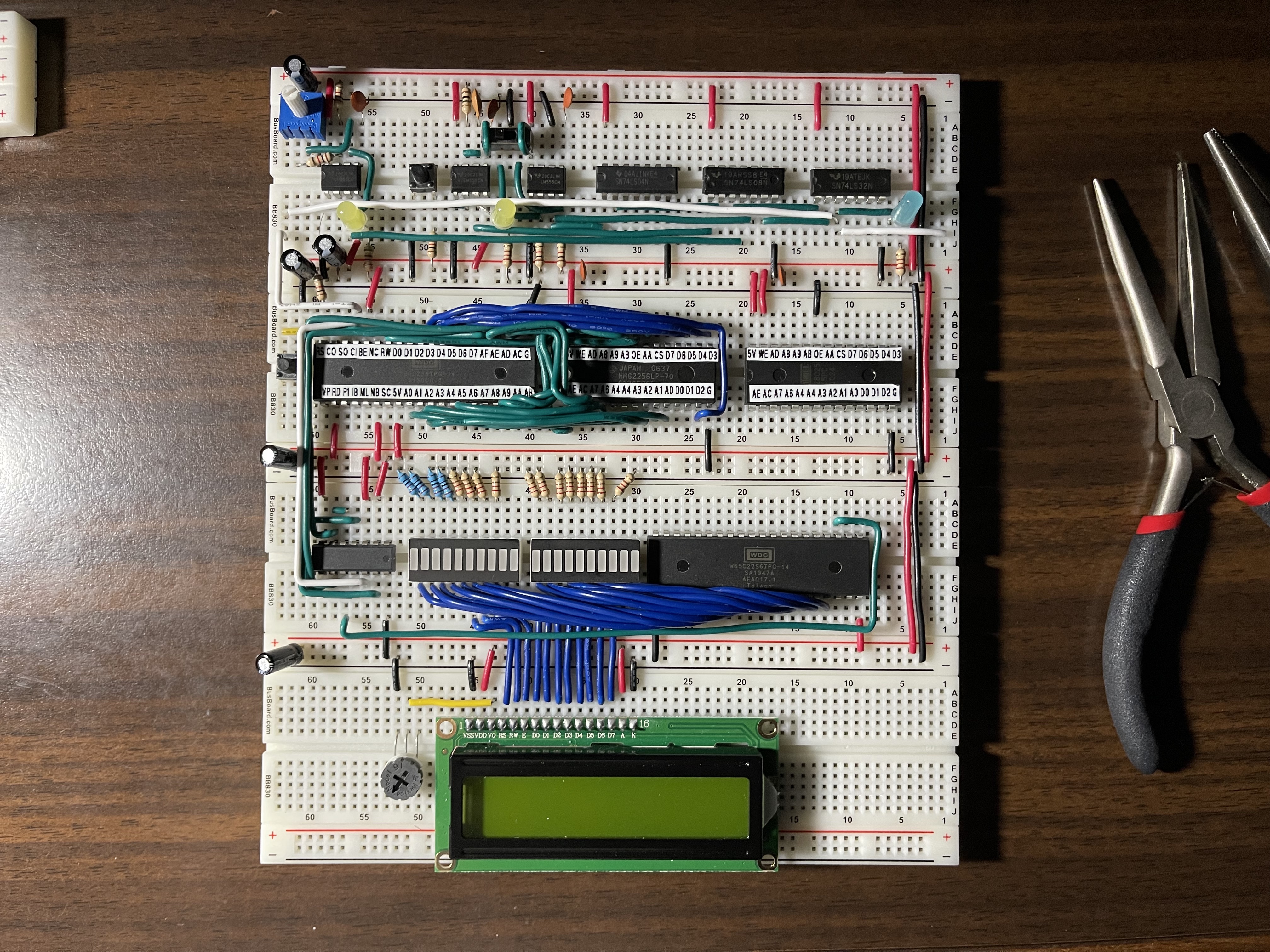
I also had the bright idea to label the pins on the ICs so that I wouldn’t have to constant refer back to their datasheets. That was a huge improvement in both efficiency and accuracy. Here’s the state of the board with all the labels and half of the final wiring done:
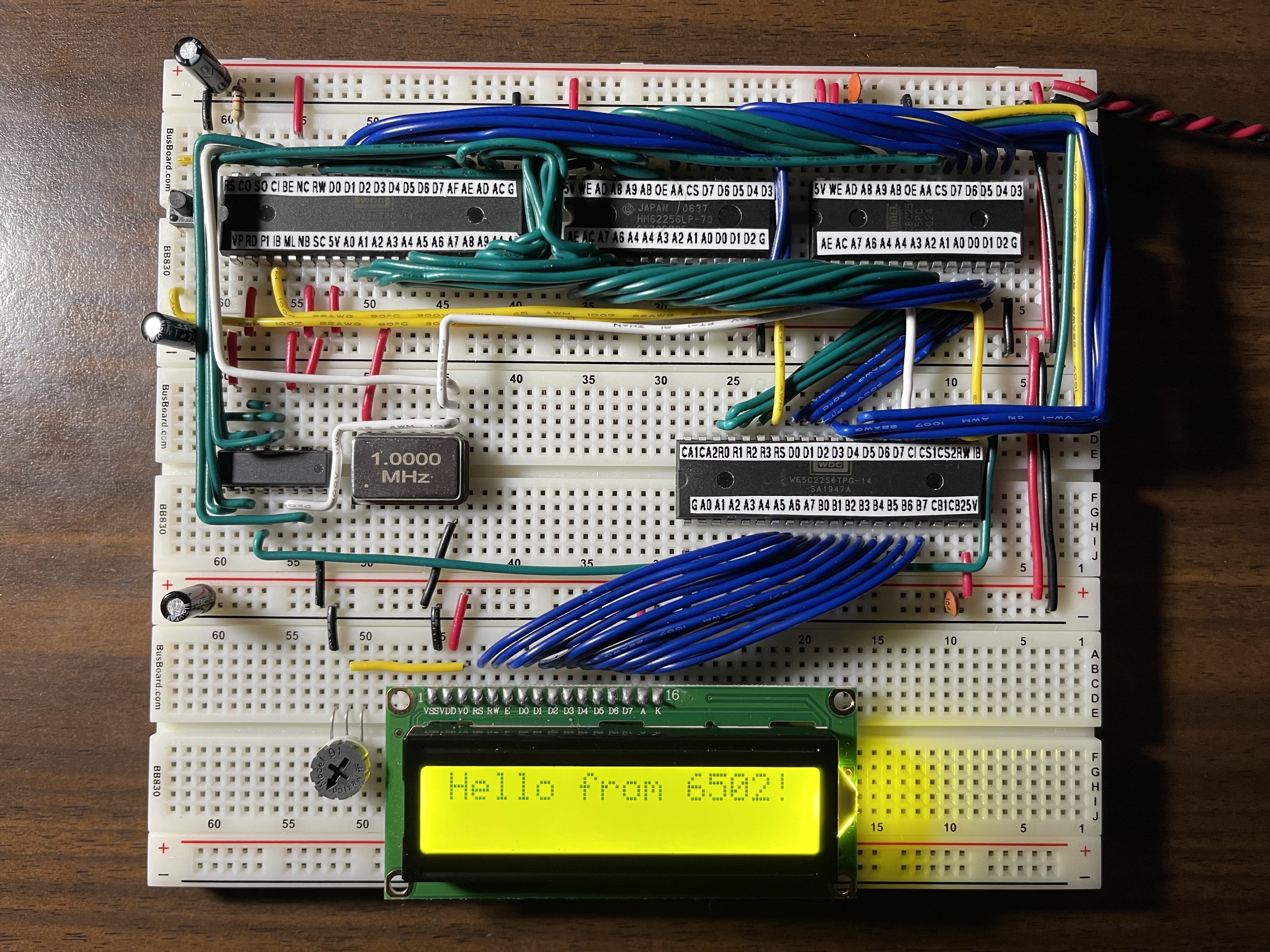
After getting all of the wiring done, I had it work again but now with a stack! The final step is to remove the clock module, which runs pretty slowly, and install a real crystal oscillator running at a blistering 1MHz. Unfortunately, I ran into issues running a full speed where I’d only see the last two or three characters of the string on the LCD. After a good deal of debugging, I discovered that the voltage on the output pins between the LEDs and the LCD was really low, so I removed the LEDs and everything worked again! My hypothesis is that the resistors were restricting the voltage too much. With the final problem solved, we have a working 6502-based computer runing at full speed!
Next, I’m going to give Ben’s 8-bit computer build a try.